Supersonic Airflow Simulation
Background
To graduate from the University of Alabama’s Aerospace Engineering Masters program, I must complete a culminating experience that engages me in research related to the coursework I completed throughout the program. In August of 2019, I began this experience under the Dr. Paul Hubner.
Dr. Hubner and his research team are currently engaged in an effort to simultaneously measure the stress and strain of surfaces in supersonic flow through the combined use of pressure sensitive paints and photoelastic coatings. The researches are covering flat plates with the paints and coatings. Those plates are then placed in the university’s supersonic wind tunnel. Flow is moved over the plates at a speed of Mach 3. Due to the high speeds, the plates deflect, and the stress and strain induced by this deflection can be evaluated by illuminating the paints and coatings. A diagram of the experimental setup and the expected flow characteristics can be seen in Figure 1.
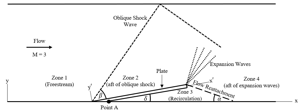
To aid in the process, Dr. Hubner tasked me with investigating the pressures, stresses, strains, and deflections that will occur in the test setup. There are four plate thicknesses that I are being evaluated during this research (1.6 mm, 3.2 mm, 4.1 mm, and 4.8 mmm).
1D Theory MATLAB Script
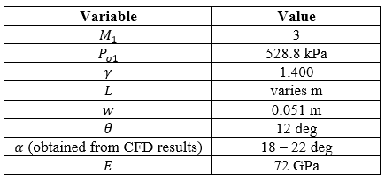
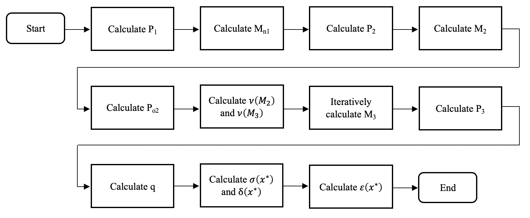
To provide initial estimates of the desired values, I utilized one-dimensional compressible flow and linear beam mechanics theory to estimate the stress, strain and deflection across the flap. To simplify calculations and provide a preliminary analysis, I assumed that the pressures above and below the flap were constant across the surface. I implemented these methodologies and assumptions into a MATLAB script.
The assumptions and input values included in the script are shown in Table 1, and the flowchart of the script is shown in Fig. 2.
The results from the MATLAB script are shown below in Table 2. The script was executed at varying flap thicknesses and reattachment angles. The reattachment angles were found from the CFD results discussed in the next section. As expected, the 1.6 mm thick flap experiences the highest stress, strain and deflection. The MATLAB script also provided pressure values above and below the plate. All values are valuable, as they provide a validation mechanism for the CFD results.

CFD Results
Geometry Development
To gain further precision for my pressure and deflection estimates, I continued my research using the ANSYS Fluent solver. To begin this process, I created a 2D geometry in ANSYS SpaceClaim. The geometry was constrained to simulate the geometry of the supersonic wind tunnel in which the experimentation is conducted. The tunnel is 0.0762 m in height, and it has 1.712 m of tunnel extending past the test area. The simulation geometry was designed with the four flap thicknesses of 1.6, 3.2, 4.1, and 4.8 mm. This is shown below in Figure 3.
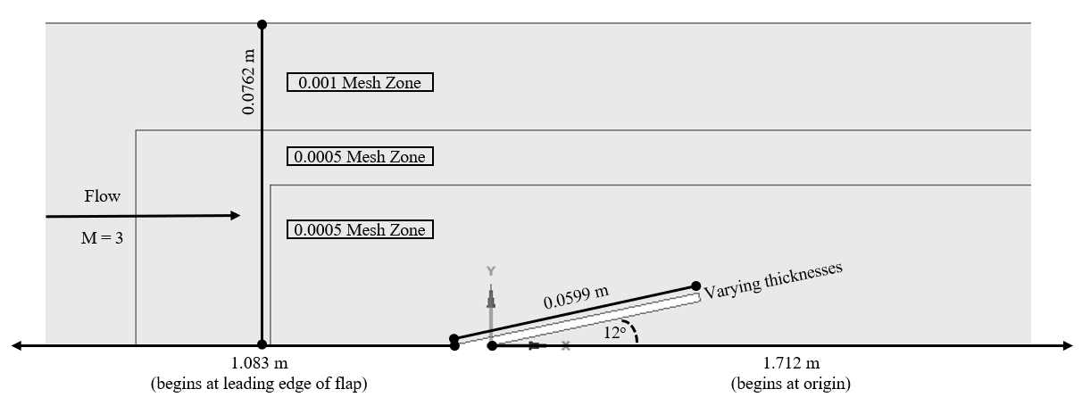
The geometry includes three zones that can be independently meshed. Additionally, it includes a tunnel length of 1.083 m ahead of the flap’s leading edge. This was added to the geometry to account for the length needed to develop the boundary layer expected in the experimentation. While the current simulation is inviscid, viscous effects will be accounted for in future simulations, and the geometry was designed to be robust for inviscid and viscous simulations.
Fluent Results – Undeformed Geometry
Once the geometry was meshed, I imported it into the ANSYS Fluent solver. The inputted conditions of the simulation were designed to imitate the real experiment. The conditions utilized in the simulation are shown in Table 3.
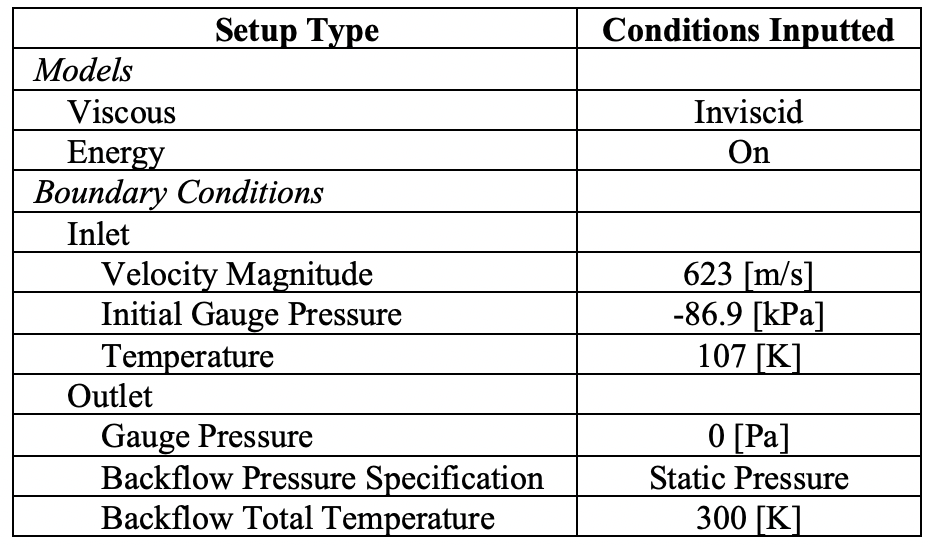
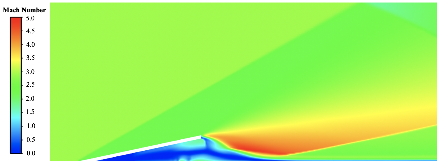
Once the simulation conditions shown in Table 3 were inputted into the solver, simulations for the 1.6 mm, 3.2 mm, 4.1 mm, and 4.8 mm flaps were conducted for approximately 20,000 iterations each. After the simulations were conducted, flow visualizations were conducted. The plots of the flow’s Mach number for the 1.6 mm thickness is shown below in Fig. 4. The color scale, shown to the left of the flow visualizations, begins at Mach 0 (blue) and ends at Mach 5 (red).
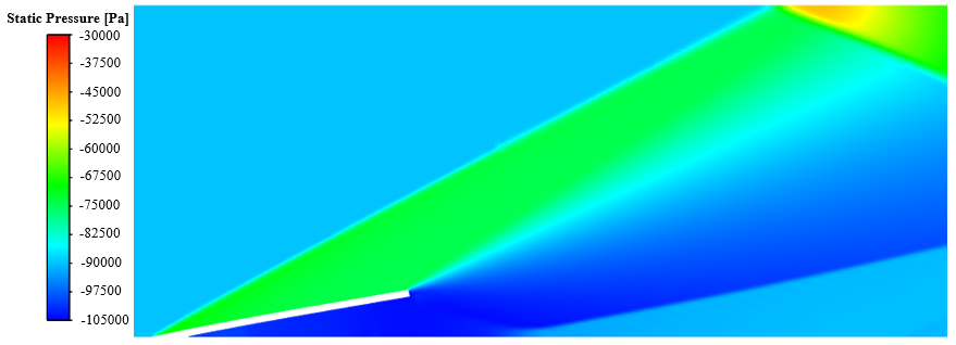
The plots of the flow’s static gauge pressure for the 1.6 mm thickness is shown below in Fig. 5. The color scale, shown to the left of the flow visualizations, begins -105 kPa (blue) and ends at -30 kPa (red).
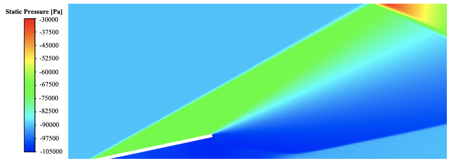
All simulations demonstrated the anticipated effects of oblique shock waves, reflections, and expansion fans. From the Mach contours, an estimation of the reattachment angle was determined. A comparison of the average pressure above and below the flap from the 1D MATLAB script (using this reattachment angle) and the 2D ANSYS Fluent simulations is shown in Table 4.

By viewing Table 5, all flap thicknesses yielded similar pressure distributions. Additionally, the pressure distribution above the flap is similar when comparing the 1D theory to the 2D CFD solver. However, the pressure distribution below the flap is significantly different when comparing the 1D theory to the 2D CFD solver. This a characteristic of the inviscid solver’s inability to adequately model the recirculation zone below the flap and the 1D flow over-simplification.
Deformed Flap Results
As mentioned previously, the flow induced on the flat plate will cause the plate to deflect. Due to this deflection, a new pressure distribution will appear above and below the plate. This cyclical effect on the plate’s deflection is analyzed in this section.
The net pressure distribution on the flap, assuming a constant distribution on the upper and lower surfaces, will cause the flap to deflect. For purpose of simplicity, I assumed the pressure distribution on the top and bottom surfaces of the undeformed flap were constant (averaged over each surface). This deflection will subsequently cause a different and varying pressure field over the surface, which would cause a different deflection and re-circulation zone. In a steady-state case, an equilibrium pressure (aerodynamic) and deflection (structural) distribution would be obtained. A combined fluid-structure solver is necessary to efficiently determine this steady-state condition. For the purposes of this project, the next iteration (secondary) deflection is calculated to compare the difference with the first iteration deflection.
The fluid-structure effect will be most pronounced on the 1.6 mm plate, as it is the thinnest. To calculate the first deflection, I calculated the pressure above and below the plate using the 1D theory MATLAB script. These values were calculated to be 33.69 kPa and 1.85 kPa, respectively. These values yield a net pressure distribution above the flap of 31.8 kPa. Using this distribution, the plate can be treated as a cantilever beam, shown in Fig. 6.

I calculated the deflection and slope of the flap’s midline using the pressure distribution, and these values were used to calculate the deflection along the top and bottom of the flap. This methodology yielded a tip deflection of 1.6 mm.
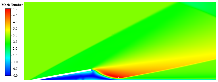
From the calculations mentioned, I created the geometry of the deformed flap’s shape and imported into a 2D geometry. I then simulated it with the same entry conditions as the simulations of the undeformed shape. The Mach number and static gauge pressure flow visualizations are shown below in Fig. 7 and 8, respectively.
The pressure distribution expressed on the deflected flap is shown below in Fig. 9. While the upper and lower surface pressures generally decrease from leading to trailing edge, the net pressure is relatively constant across the length of the flap.
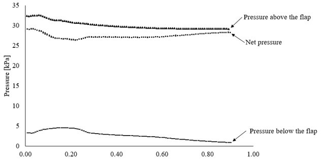
The results from the first deformation yield an approximately uniform net pressure distribution but less than the initial net pressure distribution in the undeformed state. I utilized the same methodology used to create the first deflection to create the geometry for the secondary deflection of the flap. A comparison of the three midlines for the undeflected flap, first deflection, and second deflection are visualized in Fig. 10. By viewing the figure, the first and second deflections are nearly equivalent, indicating the multiple of iterations would not be necessary for convergence. The tip deflections for the first and second iterations are 1.6 and 1.4 mm, respectively.
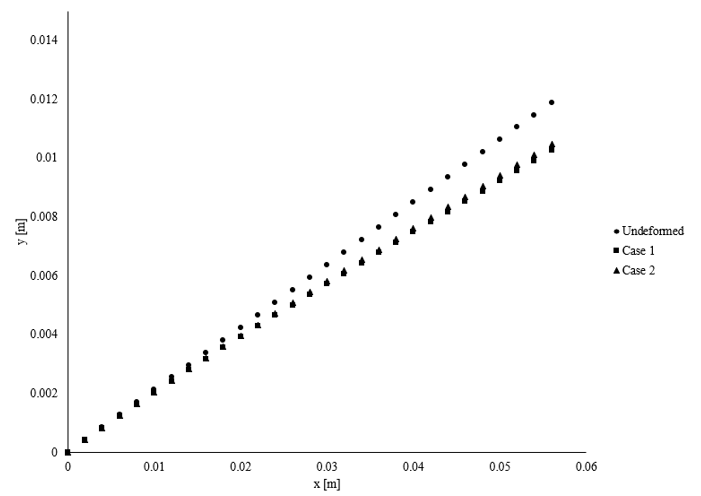
The net pressure distribution expressed on the secondary deflection yielded an approximately uniform pressure values above and below the flap. The average pressure above the plate was 30.7 kPa, and the average pressure below the plate was 4.03 kPa – yielding a uniform pressure distribution of approximately 26.6 kPa. Therefore, if this iterative process was continued, it is anticipated that the 1.6 mm flap will experience a deflection of approximately 1.3 to 1.4 mm.
Summary
This paper demonstrates a preliminary analysis to size a flap in supersonic flow. The use of 1D compressible flow and linear beam mechanics theory provided useful estimates of the stress, strain, and deflection a flap would experience at varying thicknesses. The use of 2D simulations in ANSYS Fluent demonstrated the viability of utilizing CFD solver to further refine the estimation methodology. Furthermore, this investigation has provided the research team with estimates of the deflection experienced by the 1.6 mm flap and the pressure distribution enacted on the deflected flap. In the future, the investigators could refine the model using viscous or 3D CFD solver models in order to better imitate real-world effects the flaps will experience in Mach 3 flow.
The full research paper is located here.