Solar Augmented UAV
As required by the Accreditation Board of Engineering and Technology (ABET), every student graduating with a bachelors degree in aerospace engineering must take part in a senior design project. This year, my team and I were tasked with creating a solar-augmented UAV. The mission requirements are shown below.
Objective: design, build and fly a small UAS demonstrating high endurance and incorporating the use of solar energy and capable of carrying a payload up to 120 g.
- The aircraft, when on the ground, must fit inside a 2 m diameter by 0.5 m high cylinder.
- The aircraft must be electric powered.
- The aircraft must be hand or rail launched.
- The aircraft in final flight configuration, outside and on the ground, must be capable of fully charging the depleted aircraft battery.
- The aircraft must complete a forward-flight mission:
- cruise demonstrating both left and right turns; capped at 30 minutes
- demonstrate in-flight battery charging with full or partial payload
- land within 20 m of the take-off location
- sustain no damage to aircraft or payload that prevents a second flight within 15 mins
- The payload, up to two medium eggs, must be housed in a separate capsule that can be easily inserted, secured and removed from the aircraft within 3 minutes.
- The cost of the aircraft may not exceed $800.
Because there is another team in our program that we are competing against, there is a scoring equation to be used if both teams are able to build an operational aircraft. This equation is shown below.
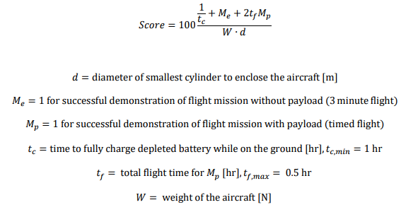
By viewing the scoring equation, one can see that it serves us to minimize the weight and wingspan of the aircraft. With these constraints, we have created a design for the aircraft that we believe will work flawlessly. Serving as team lead, my main responsibility has been keeping the team moving forward through the preliminary and critical design phases. In addition, it was mostly my duty to create the CAD model of the aircraft. I did this using Solidworks 2017. My chief engineer and friend, Lucas Lyons, created the horizontal stabilizer, vertical stabilizer, elevator, and rudder shown in the model.
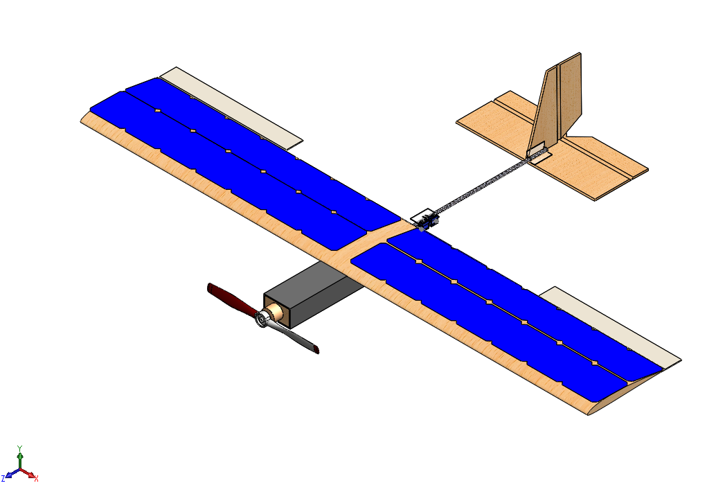
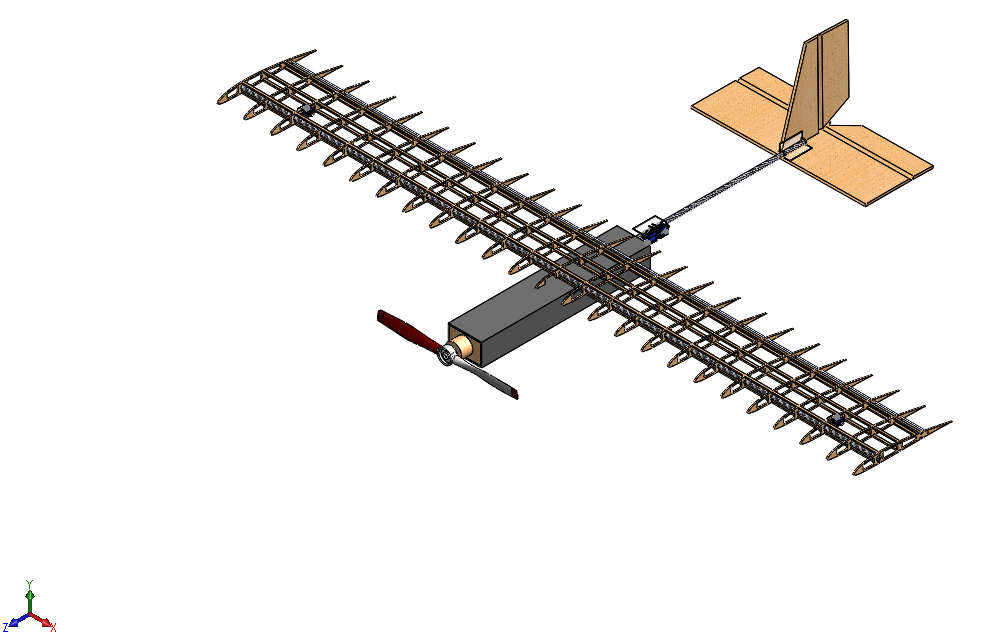
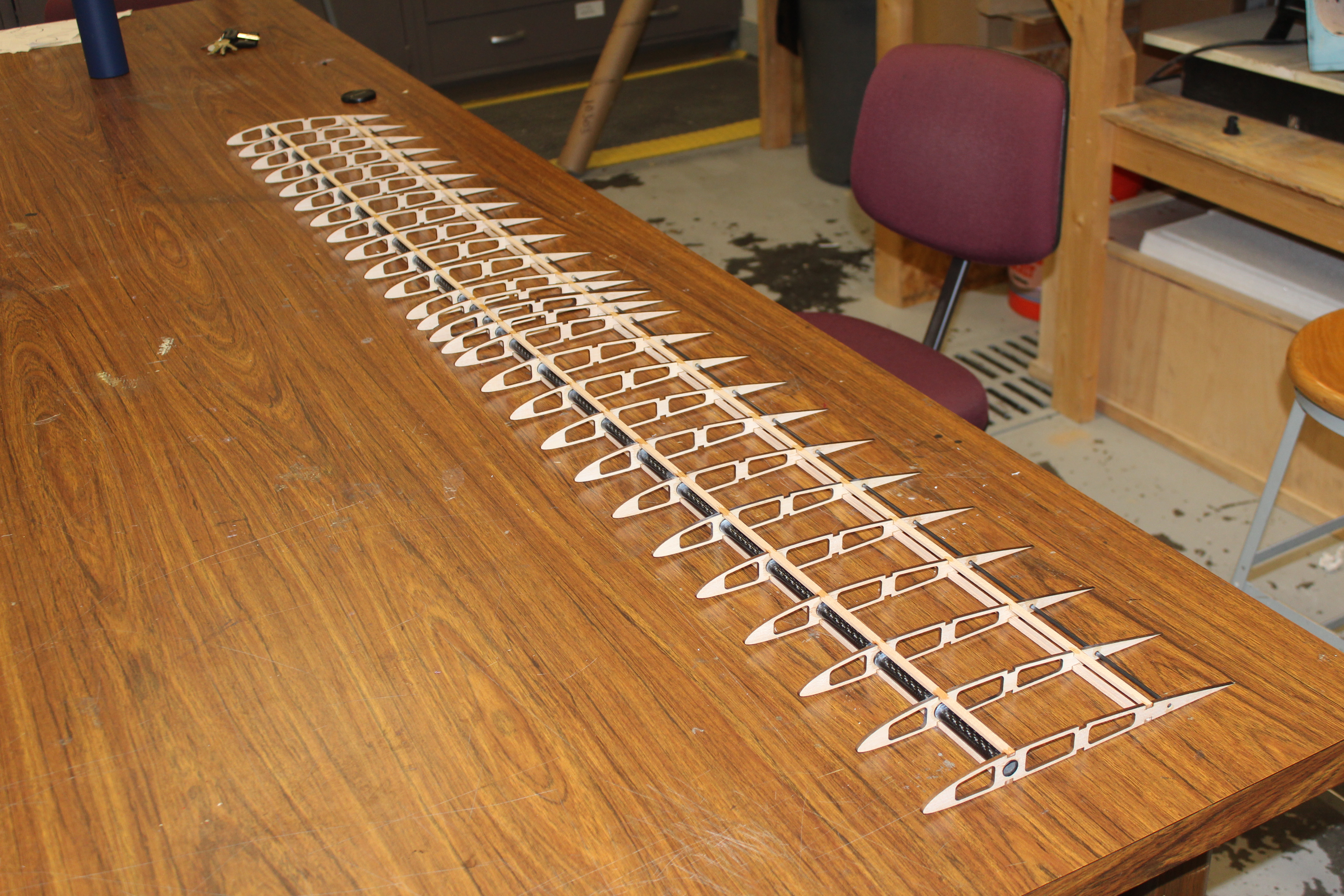
The wingspan was decided to be 72 in. This was chosen due to the necessity of 28 solar cells to be placed on the aircraft. By using 28 solar cells, the aircraft will generate enough electricity to flow into the 3-cell battery that we are using. The solar cells are 5 inch by 5 inch squares, and, as seen above, there are 4 rows of 7 cells placed on the wing. The 2 inch space in the center of the wing was created to allow room for wrapping rubber bands for wing and tail attachment to the fuselage. This method of attachment was inspired by the Youtuber “ExperimentalAirlines” and is shown here. The wing is made out of a carbon fiber main spar, a fiberglass secondary spar, and balsa ribs and stringers. The tail is made out of balsa wood, and the fuselage is made out of foamboard – also inspired by ExperimentalAirlines.
Currently, we are still building the aircraft. We have built the frame for the wing, and the next step is to create our tail and fuselage. Pretty soon, our electronics should be coming in. Once this happens, we will begin assembling the aircraft in its entirety.
UPDATE (PART 1): The UAV was able to complete its mission on the morning of April 25th, 2018. The flight description is provided in the following paragraph.
In under three minutes, the aircraft was assembled into final flight configuration with the payload placed inside. After arming the control surfaces, the propulsion system was tested to ensure that the adapter would remain attached. It was decided that solar charging capabilities would not be demonstrated at this time due to unfavorable weather conditions, as the cells’ low voltage would have drained the battery instead of charging it. Although there was light wind present, the launch went smoothly. The aircraft first gained altitude flying into the wind with a slight cross-wind. Once at a stable altitude, the pilot stayed on a forward path, banking left to demonstrate a left turn ninety degrees from the original heading. Once level flight was established again, a right turn was demonstrated by banking the aircraft in the opposite direction. The wind then caused the aircraft to accelerate quickly, and the pilot entered a wide turning radius to begin the landing phase. Upon final approach, the aircraft slowed down and the pilot began to enter a flare 3-5 ft above the ground. Once within the twenty-meter diameter landing circle, the pilot pitched the aircraft up to establish a soft belly landing. This flight was completed in 49 seconds. The flight path is shown below.
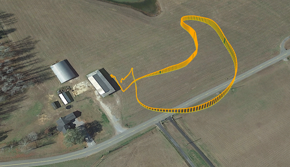
UPDATE (PART 2): A second flight was completed on the morning of May 5th, 2018. The flight description is provided in the following paragraph.
During this flight, the pilot made multiple passes across the flight demonstration grounds, and he demonstrated left and right turns. The solar array was able to generate 15.67 volts in direct sunlight. Via the ground station, the change in battery power was noticeable. As the aircraft banked into the sunlight, the battery voltage increased. As it backed out of the sunlight, the voltage decreased. The cruise velocity was displayed on the ground station at 35 ft/s. It should be noted that this is 10 ft/s faster than the estimated cruise velocity. Moreover, the aircraft appeared to be somewhat underpowered in flight. Therefore, a few conjectures have been made. Firstly, future models of this aircraft should use a higher kV motor. Also, to increase power, a 4-cell battery should be used. At full charge, a 4-cell battery would have 16.8 volts. Because of this, the aircraft would need more solar cells. The electronics lead believes that two more solar cells should be added at each wingtip, resulting in an 82 in wingspan. Future iterations of this aircraft should have these features.
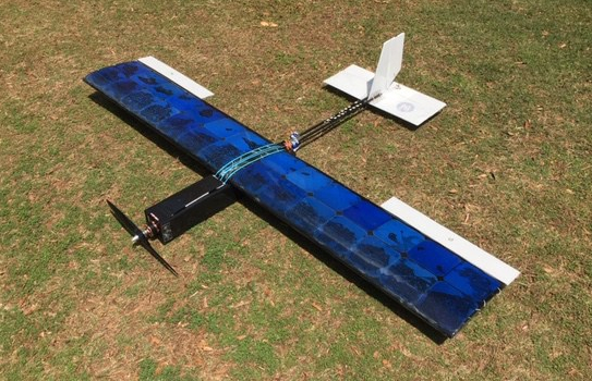
Overall, the undertaking was a success. The aircraft completed all of its mission requirements, and my team and I are more skilled engineers because of the project.